
TM 5-2410-240-23-2
0158
REMOVAL CONTINUED
N OT E
Tag all hoses and fittings to aid installation.
Use a container to catch any fluid that may drain from hoses or system. Dispose of fluid
IAW local policy and ordinances. Ensure all spills are cleaned up.
Note routing of hoses to aid installation.
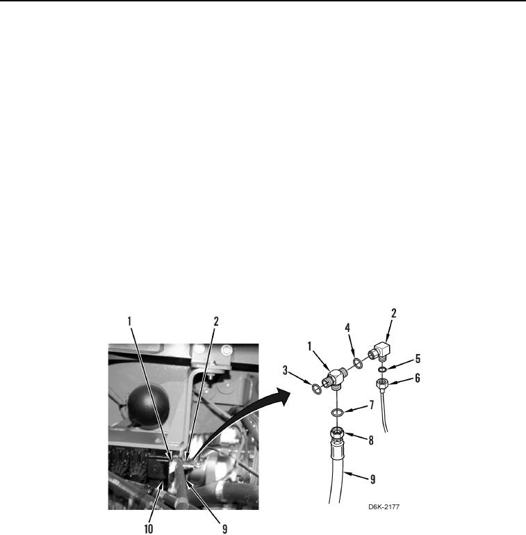
13. Disconnect tube (Figure 6, Item 6), remove O-ring (Figure 6, Item 5) from elbow (Figure 6, Item 2), and position
tube (Figure 6, Item 6) aside. Discard O-ring.
14. Disconnect elbow (Figure 6, Item 2) and remove O-ring (Figure 6, Item 4) from tee (Figure 6, Item 1). Discard
O-ring.
15. Disconnect hose fitting (Figure 6, Item 8) from tee (Figure 6, Item 1), remove O-ring (Figure 6, Item 7) from tee
(Figure 6, Item 1), and position hose (Figure 6, Item 9) aside. Discard O-ring.
N OT E
Note position of tee to aid installation.
16. Remove tee (Figure 6, Item 1) and O-ring (Figure 6, Item 3) from valve bank (Figure 6, Item 10). Discard O-
ring.
Figure 6. Valve Bank and Hose.
0158