
TM 5-2410-240-23-2
0158
INSTALLATION CONTINUED
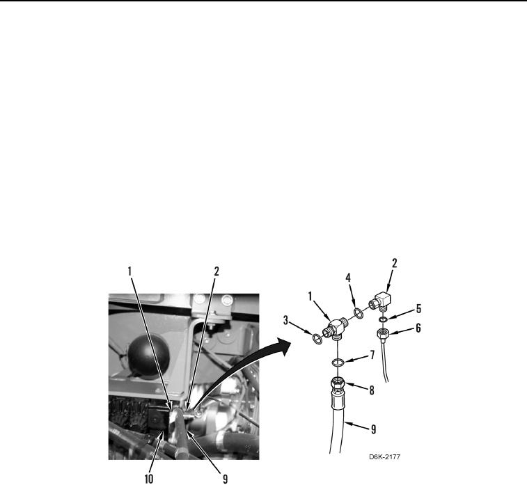
4. Remove caps and install new O-ring (Figure 8, Item 3) on tee (Figure 8, Item 1).
N OT E
Install tee fitting as noted during removal.
5. Install tee (Figure 8, Item 1) on valve bank (Figure 8, Item 10).
N OT E
Install hose as noted during removal.
6. Install new O-ring (Figure 8, Item 7) on tee (Figure 8, Item 1) and position hose (Figure 8, Item 9) on machine.
7. Connect hose fitting (Figure 8, Item 8) to tee (Figure 8, Item 1).
8. Install new O-ring (Figure 8, Item 4) and elbow (Figure 8, Item 2) on tee (Figure 8, Item 1).
9. Install new O-ring (Figure 8, Item 5) on elbow (Figure 8, Item 2) and install tube (Figure 8, Item 6) on machine.
Figure 8. Valve Bank and Hose.
0158