
TM 5-2410-240-23-2
0158
INSTALLATION CONTINUED
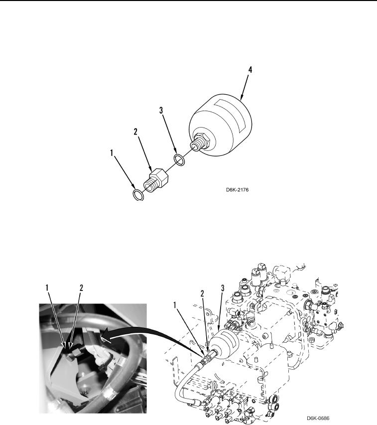
10. Remove caps and install new O-ring (Figure 9, Item 3) and adapter (Figure 9, Item 2) on accumulator
(Figure 9, Item 4).
11. Install new O-ring (Figure 9, Item 1) on adapter (Figure 9, Item 2)
Figure 9. Accumulator.
0158
12. Position accumulator assembly (Figure 10, Item 3) on machine and install nut (Figure 10, Item 1) on adapter
(Figure 10, Item 2).
Figure 10. Accumulator Assembly.
0158