
TM 5-2410-240-23-2
0169
RIGHT DRIVE LOOP HOSE REMOVAL CONTINUED
C AU T I O N
Cap or plug all hydraulic hose ends and fittings during removal to protect against
contamination. Failure to follow this caution may cause damage to equipment.
N OT E
Tag and mark hose and fitting to aid installation.
Use a container to catch any fluid that may drain from hose or system. Dispose of fluid
IAW local policy and ordinances. Ensure all spills are cleaned up.
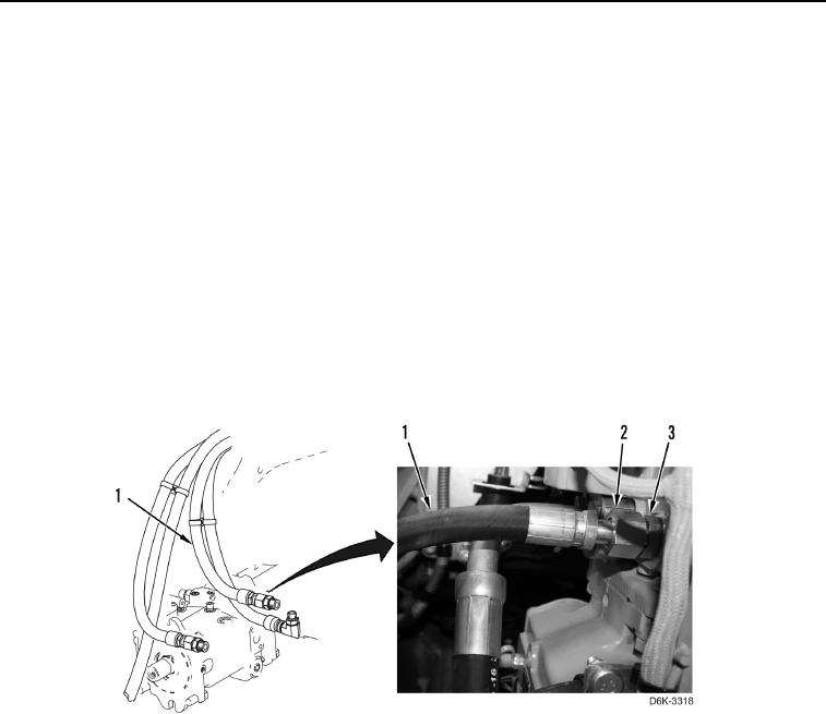
5. Loosen fitting (Figure 3, Item 2) and disconnect hose (Figure 3, Item 1) from connector (Figure 3, Item 3).
N OT E
Note routing of hose to aid installation.
6. Remove hose (Figure 3, Item 1) from machine.
Figure 3. Hose and Fittings.
0169
END OF TASK