
TM 5-2410-240-23-2
0169
LEFT DRIVE LOOP HOSE REMOVAL CONTINUED
C AU T I O N
Cap or plug all hydraulic hose ends and fittings during removal to protect against
contamination. Failure to follow this caution may cause damage to equipment.
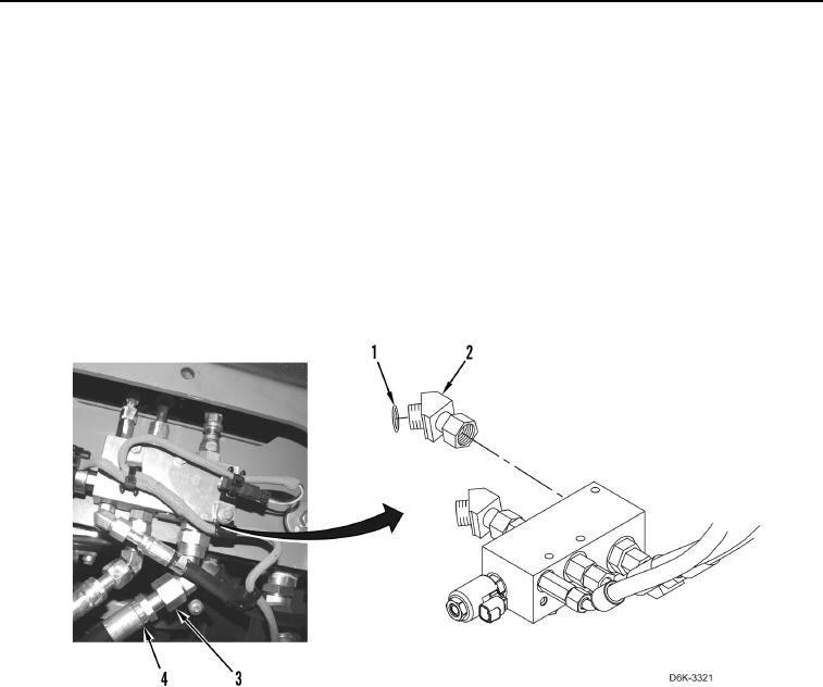
12. Loosen fitting (Figure 7, Item 3) and disconnect hose (Figure 7, Item 4) from connector (Figure 7, Item 2).
13. Remove O-ring (Figure 7, Item 1) from connector (Figure 7, Item 2). Discard O-ring.
N OT E
Note routing of hose to aid installation.
14. Remove hose (Figure 7, Item 4) from machine.
Figure 7. Hose, Fittings, O-rings, and Manifold.
0169
END OF TASK
CLEANING AND INSPECTION
000169
Clean and inspect all parts IAW Mechanical General Maintenance Instructions (WP 0282).
END OF TASK