• Home
  • Download PDF
  • Order CD-ROM
  • Order in Print
Figure 5. Hoses and Retaining Hardware.
Figure 7. Hose, Fittings, O-rings, and Manifold.

Field Maintenance Manual 2 D6K Dozer Type I With Winch and Type II With Ripper
Page Navigation
  1210    1211    1212    1213    1214  1215  1216    1217    1218    1219    1220  
img
.
TM 5-2410-240-23-2
0169
LEFT DRIVE LOOP HOSE REMOVAL CONTINUED
N OT E
Note location of clamps to aid installation.
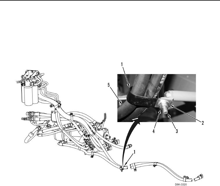
10. Remove nut (Figure 6, Item 4), washer (Figure 6, Item 2), bolt (Figure 6, Item 3), and clamp (Figure 6, Item 1)
from machine.
11. Remove four clamps (Figure 6, Item 1) from hoses (Figure 6, Item 5).
Figure 6. Hose and Retaining Hardware.
0169
0169-9


Privacy Statement
Press Release
Contact

© Copyright Integrated Publishing, Inc.. All Rights Reserved.