
TM 5-2410-240-23-2
0169
LEFT DRIVE LOOP HOSE INSTALLATION
000169
N OT E
Hydraulic hoses, clamps, and fittings are all installed using the same general method. This
procedure covers installation of one hydraulic hose assembly on machine.
Install hose as noted during removal.
1. Install hose (Figure 7, Item 9) on machine.
2. Apply lubricating oil on new O-ring (Figure 7, Item 1).
3. Install O-ring (Figure 7, Item 1) on connector (Figure 7, Item 2).
4. Connect hose (Figure 7, Item 4) to connector (Figure 7, Item 2) and tighten fitting (Figure 7, Item 3).
N OT E
Install clamps as noted during removal.
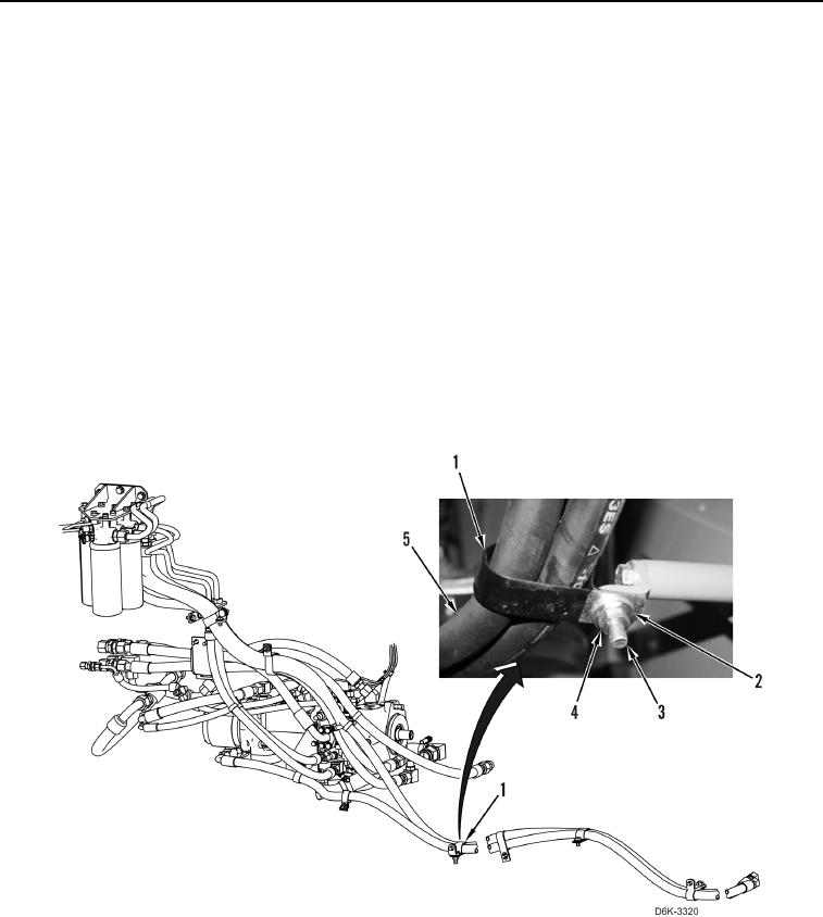
5. Install four clamps (Figure 8, Item 1) on hoses (Figure 8, Item 5).
6. Install four clamps (Figure 8, Item 1), bolts (Figure 8, Item 3), washers (Figure 8, Item 2), and nuts (Figure 8,
Item 4) on machine.
Figure 8. Hose and Retaining Hardware.
0169