
TM 5-2410-240-23-2
0169
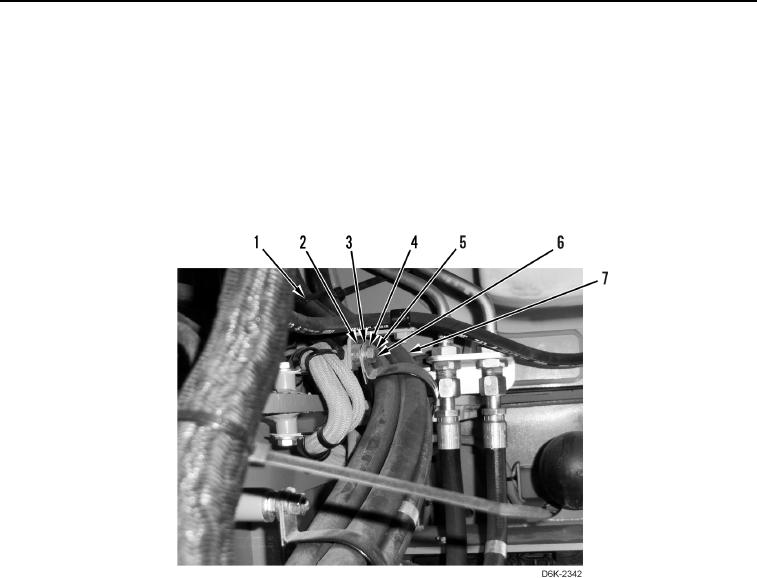
LEFT DRIVE LOOP HOSE REMOVAL CONTINUED
N OT E
Note location of tiedown straps to aid installation.
7. Remove tiedown straps (Figure 5, Item 1) from hoses (Figure 5, Item 7). Discard tiedown straps.
8. Remove two nuts (Figure 5, Item 5), washers (Figure 5, Item 4), clamps (Figure 5, Item 3), and spacers
(Figure 5, Item 2) from studs (Figure 5, Item 6).
9. Remove two clamps (Figure 5, Item 3) from hoses (Figure 5, Item 7).
Figure 5. Hoses and Retaining Hardware.
0169