
TM 5-2410-240-23-2
0169
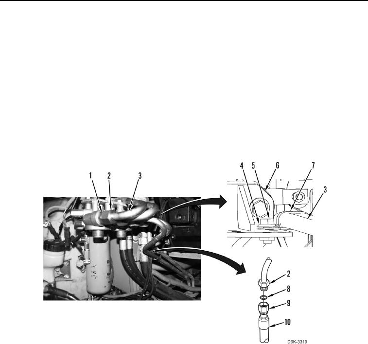
LEFT DRIVE LOOP HOSE INSTALLATION CONTINUED
N OT E
Remove caps or plugs from all hydraulic hose ends and fittings prior to installation.
10. Apply lubricating oil on new O-ring (Figure 10, Item 8).
11. Install O-ring (Figure 10, Item 8) on tube (Figure 10, Item 3).
12. Connect tube (Figure 10, Item 3) to connector (Figure 10, Item 1).
13. Connect hose (Figure 10, Item 10) to tube (Figure 10, Item 3).
14. Install clamp (Figure 10, Item 7) on tubes (Figure 10, Item 3).
15. Tighten two fittings (Figure 10, Items 2 and 9).
16. Install clamp (Figure 10, Item 7), washer (Figure 10, Item 4), and bolt (Figure 10, Item 5) on bracket (Figure 10,
Item 6).
Figure 10. Hose and Fittings.
0169
END OF TASK