
TM 5-2410-240-23-2
0169
LEFT DRIVE LOOP HOSE INSTALLATION CONTINUED
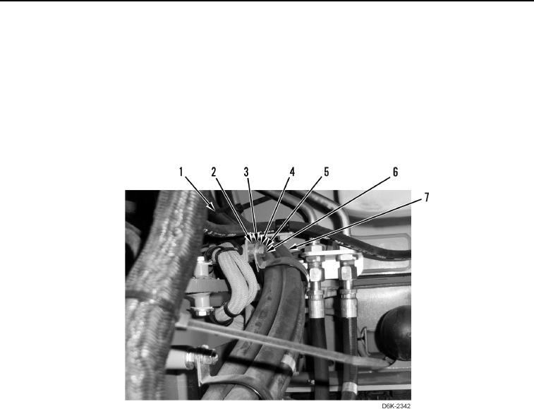
7. Install two clamps (Figure 9, Item 3) on hoses (Figure 9, Item 7).
8. Install two spacers (Figure 9, Item 2), clamps (Figure 9, Item 3), washers (Figure 9, Item 4), and nuts (Figure 9,
Item 5) on studs (Figure 9, Item 6).
N OT E
Install tiedown straps as noted during removal.
9. Install new tiedown straps (Figure 9, Item 1) on hoses (Figure 9, Item 7).
Figure 9. Hoses and Retaining Hardware.
0169