
TM 5-2410-240-23-2
0172
RIGHT SIDE LIFT TUBES REMOVAL CONTINUED
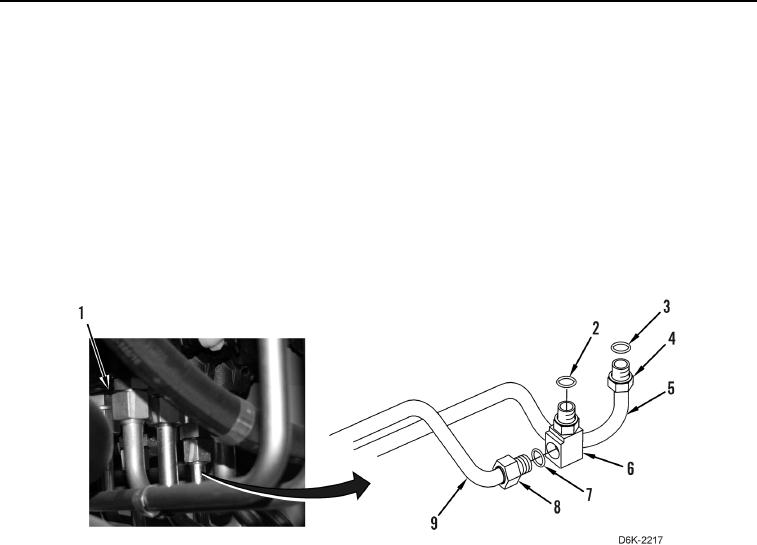
4. Loosen tube nut (Figure 8, Item 4) from valve bank (Figure 8, Item 1) and remove O-ring (Figure 8, Item 3)
from tube assembly (Figure 8, Item 5). Discard O-ring.
5. Loosen tube nut (Figure 8, Item 8) from elbow (Figure 8, Item 6) and remove O-ring (Figure 8, Item 7) from
tube assembly (Figure 8, Item 9). Discard O-ring.
N OT E
Note position of fitting to aid installation.
6. Remove elbow (Figure 8, Item 6) and O-ring (Figure 8, Item 2) from valve bank (Figure 8, Item 1). Discard
O-ring.
7. Remove two right side lift tubes (Figure 8, Items 5 and 9) from machine.
Figure 8. Tube Assembly.
0172
END OF TASK
CLEANING AND INSPECTION
000172
Clean and inspect all parts IAW Mechanical General Maintenance Instructions (WP 0282).
END OF TASK