
TM 5-2410-240-23-2
0172
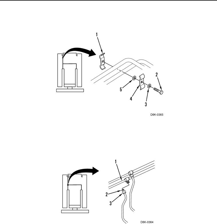
RIGHT SIDE LIFT TUBES INSTALLATION CONTINUED
5. Install clamp (Figure 10, Item 1), washer (Figure 10, Item 5), clamp (Figure 10, Item 4), washer (Figure 10,
Item 3), and bolt (Figure 10, Item 2) on machine.
Figure 10. Clamp.
0172
6. Install two new O-rings (Figure 11, Item 2) on two right side lift tubes (Figure 11, Item 1).
7. Connect two left side lift tubes (Figure 11, Item 3) to two right side lift tubes (Figure 11, Item 1) and install right
bulkhead bracket. Refer to Bulkhead Bracket Installation in this work package.
Figure 11. Tube Fitting.
0172
END OF TASK