
TM 5-2410-240-23-2
0172
BULKHEAD BRACKET INSTALLATION
000172
N OT E
Brackets are all installed using the same general method. This procedure covers
installation of one bracket on machine. Repeat steps to install bracket on opposite side of
machine.
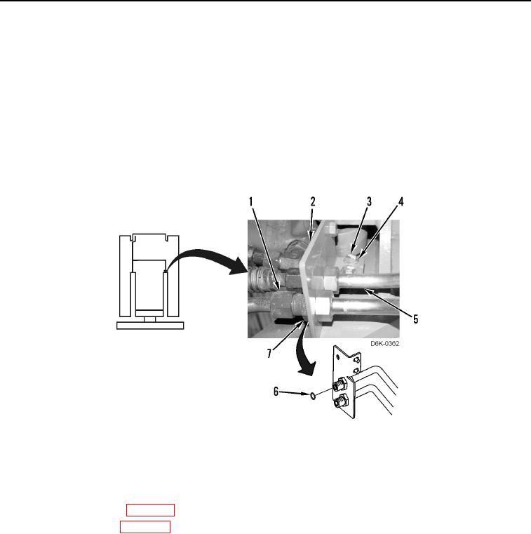
1. Position bracket (Figure 16, Item 2) on machine.
2. Install two washers (Figure 16, Item 4) and bolts (Figure 16, Item 3) on machine.
3. Install two new O-rings (Figure 16, Item 6) and bulkhead nut (Figure 16, Item 7) on two tubes (Figure 16,
Item 5), and connect two hose fittings (Figure 16, Item 1) to two tubes (Figure 16, Item 5).
Figure 16. Tube and Bracket.
0172
END OF TASK
FOLLOW-ON TASKS
000172
1. Fill with hydraulic fluid (WP 0162).
2. Install bottom guards (WP 0156).
3. Install front cab floor plate (WP 0205).
4. Install debris guards (WP 0187).
5. Verify correct operation of machine (TM 5-2410-240-10).
END OF TASK
END OF WORK PACKAGE