
TM 5-2410-240-23-2
0172
LEFT SIDE LIFT TUBES INSTALLATION CONTINUED
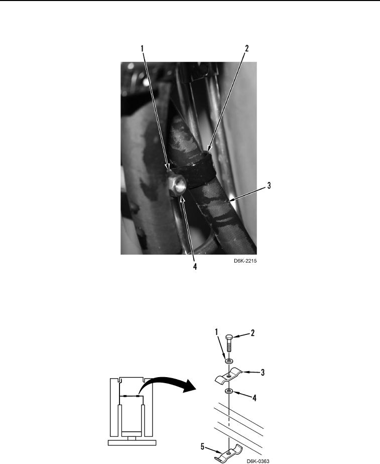
4. Position hose (Figure 14, Item 3) on machine and install clamp (Figure 14, Item 2), washer (Figure 14, Item 1),
and nut (Figure 14, Item 4) on machine.
Figure 14. Hose Clamp
0172
5. Install two clamps (Figure 15, Item 5), spacers (Figure 15, Item 4), clamps (Figure 15, Item 3), washers
(Figure 15, Item 1), and bolts (Figure 15, Item 2) on machine.
6. Install left bulkhead bracket. Refer to Bulkhead Bracket Installation in this work package.
Figure 15. Tube Clamps.
0172
END OF TASK