
TM 5-2410-240-23-2
0172
RIGHT SIDE LIFT TUBES INSTALLATION
000172
WARN I N G
Lubricating/hydraulic oils used in performance of maintenance can be very slippery.
Immediately wipe up any spills. Failure to follow this warning may result in injury to
personnel.
N OT E
Install tubes and fittings as noted during removal.
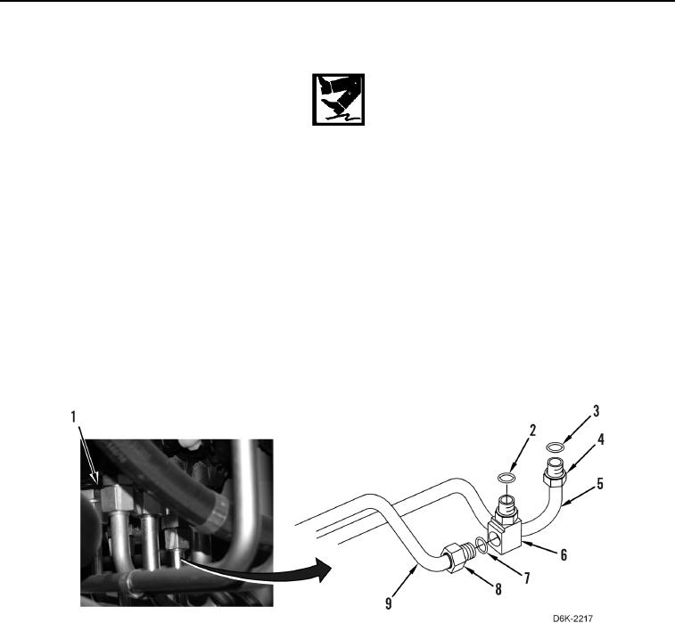
1. Remove caps and install new O-ring (Figure 9, Item 2) and elbow (Figure 9, Item 6) on valve bank (Figure 9,
Item 1).
2. Position two right side lift tubes (Figure 9, Items 5 and 9) on machine.
3. Install new O-ring (Figure 9, Item 3) on tube (Figure 9, Item 5), and connect tube nut (Figure 9, Item 4) to valve
bank (Figure 9, Item 1).
4. Install new O-ring (Figure 9, Item 7) on tube (Figure 9, Item 9), and connect tube nut (Figure 9, Item 8) to elbow
(Figure 9, Item 6).
Figure 9. Tube Assembly.
0172