
TM 5-2410-240-23-3
0232
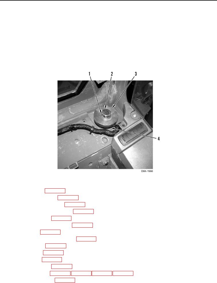
REMOVAL CONTINUED
N OT E
The following procedure is for the left side rear cab mount. Use this same procedure for
the right side rear cab mount.
24. Remove bolt (Figure 10, Item 1), washer (Figure 10, Item 2), spacer (Figure 10, Item 3), and rubber mount
(Figure 10, Item 4) from cab.
25. With assistance and using suitable lifting device, remove cab from machine and lower to flat surface.
26. Remove lifting device from cab.
Figure 10. Left Rear Cab Mount.
0232
27. Remove upper cab (WP 0284).
28. Remove lower cab panels (WP 0206).
29. Remove circuit breaker panel (WP 0203).
30. Remove lower cab wiring harness (WP 0228).
31. Remove fresh air filter (WP 0253).
32. Remove air conditioner assembly (WP 0245).
33. Remove air duct (WP 0246).
34. Remove recirculation cabin air filter (WP 0252).
35. Remove A/C hoses (WP 0248).
36. Remove A/C lines (WP 0249).
37. Remove cab trim (WP 0212).
38. Remove washer bottle (WP 0223).
40. Remove insulation foam (WP 0230).