
TM 5-2410-240-23-3
0267
INSTALLATION CONTINUED
N OT E
Remove caps or plugs from hoses, lines, and fittings.
Install hoses and lines as noted during removal.
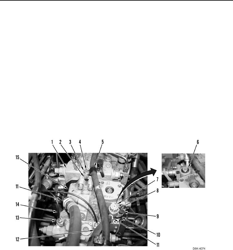
9. Connect three lines (Figure 8, Item 14) on winch piston pump (Figure 8, Item 15) and tighten tube nuts
(Figure 8, Item 13).
10. Connect two hoses (Figure 8, Item 12) on winch piston pump (Figure 8, Item 15) and tighten tube nuts
(Figure 8, Item 11).
11. Install spacer (Figure 8, Item 2), clamp (Figure 8, Item 5), washer (Figure 8, Item 3), and bolt (Figure 8, Item 4)
on right hydrostatic drive piston pump (Figure 8, Item 1).
12. Install solenoid (Figure 8, Item 8), new O-ring (Figure 8, Item 6), and nut (Figure 8, Item 7) on winch piston
pump (Figure 8, Item 15).
N OT E
Install electrical connectors and tiedown straps as noted during removal.
13. Connect harness (Figure 8, Item 9) on solenoid (Figure 8, Item 8).
14. Install new tiedown strap (Figure 8, Item 10) on solenoid (Figure 8, Item 8) and harness (Figure 8, Item 9).
Figure 8. Harness, Solenoid, Lines, and Hoses on Winch Piston Pump.
0267