
TM 5-2410-241-23-1
0020
Table 1. Powertrain Troubleshooting Procedures - Continued.
0020
MALFUNCTION
TEST OR INSPECTION
CORRECTIVE ACTION
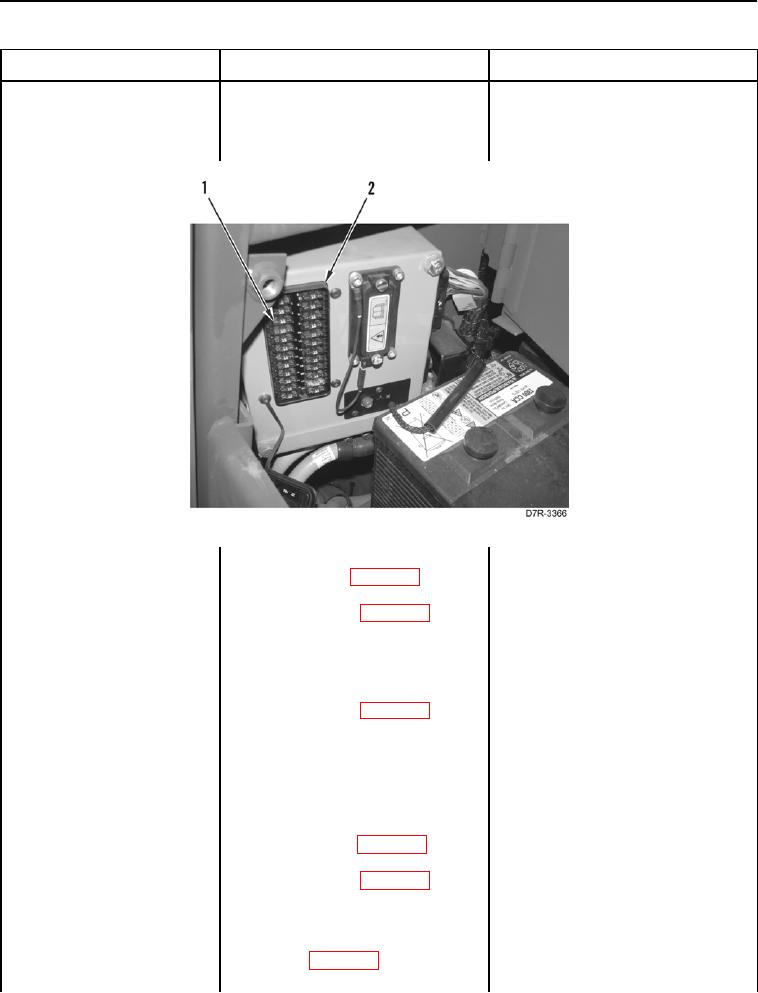
468-3 Service Brake Pedal
37. Remove Fuse # 5 (Figure 25,
Position Sensor Voltage
Item 1) from fuse panel (Figure 25,
Above Normal - Contin-
Item 2) (TM 5-2410-241-10).
ued
Figure 25. Fuse #5.
0020
38. Disconnect platform harness con-
nector MA-C3 (WP 0018, Figure
21) from fuse panel wiring harness
connector A-C1 (WP 0018, Figure
22).
39. Using a digital multimeter (WP
1. If continuity is NOT found, proceed
0296), test for continuity between
to step 40.
pin 3 on fuse panel wiring harness
2. If continuity is found, replace fuse
connector A-C1 (WP 0018, Figure
panel wiring harness (WP 0181).
22) and machine ground.
Replace Fuse #5 (TM 5-2410-241-
10). Ensure all harness connec-
tors are reconnected. Verify cor-
rect operation of machine (TM 5-
2410-241-10).
40. Disconnect platform harness con-
nector MA-C14 (WP 0018, Figure
33) from steering control harness
connector X-C1 (WP 0018, Figure
34).
41. Disconnect platform harness con-
nector MA-C13 from RH console
harness (WP 0018, Figure 158).