
TM 5-2410-241-23-1
0020
Table 1. Powertrain Troubleshooting Procedures - Continued.
0020
MALFUNCTION
TEST OR INSPECTION
CORRECTIVE ACTION
468-3 Service Brake Pedal
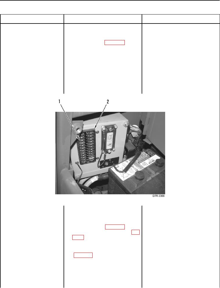
25. Using a digital multimeter (WP
1.
If continuity is found, replace pow-
Position Sensor Voltage
0296), test for continuity between
ertrain ECM (WP 0175). Install
Above Normal - Continued
pin 3 on fuse panel wiring harness
Fuse#5 on fuse panel. Ensure all
connector A-C1 (WP 0018, Figure
harness connectors are recon-
22) and left cavity of Fuse #5 (Fig-
nected. Verify correct operation of
ure 24, Item 1) on fuse panel (Fig-
machine (TM 5-2410-241-10).
ure 24, Item 2).
2.
If continuity is NOT found, replace
fuse panel harness (WP 0176).
Install Fuse #5 on fuse panel.
Ensure all harness connectors are
reconnected. Verify correct opera-
tion of machine (TM 5-2410-241-
10).
Figure 24. Fuse #5.
0020
26. Remove left platform access panel
(WP 0207).
27. Disconnect parking brake switch
connector X-C6 (WP 0018, Figure
44) from parking brake switch (WP
0018, Figure 45).
28. Disconnect forward/neutral/
reverse sensor connector X-C8
(WP 0018, Figure 49) from forward
neutral reverse sensor (WP 0237).
1. If Fuse #5 is OK, proceed to step
29. Turn ignition switch and battery
30.
disconnect switch to ON position
(TM 5-2410-241-10).
2. If Fuse #5 is blown, proceed to
step 36.