
TM 5-2410-241-23-1
0029
TEST STEP 1: GROUND CABLES CONTINUED
5. Remove engine enclosure left door guard (WP 0202).
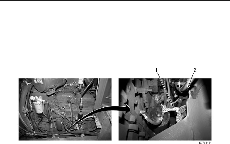
6. Using a digital multimeter (WP 0296), measure voltage between positive battery post (Figure 2, Item 1) and
ground stud on frame (Figure 2, Item 2) of starter ground strap (Figure 2, Item 1). Voltage drop should be within
1 volt of value recorded in step 3, or the ground is faulty.
a. If voltage drop is greater than 1 volt of value recorded in step 3, proceed to step 7 to isolate ground fault.
b. If voltage drop is within 1 volt of value recorded in step 3, machine ground strap to the starter is faulty.
Replace ground strap to the starter (WP 0164).
Figure 2. Starter Ground Strap.
0029