
TM 5-2410-241-23-1
0029
TEST STEP 1: GROUND CABLES CONTINUED
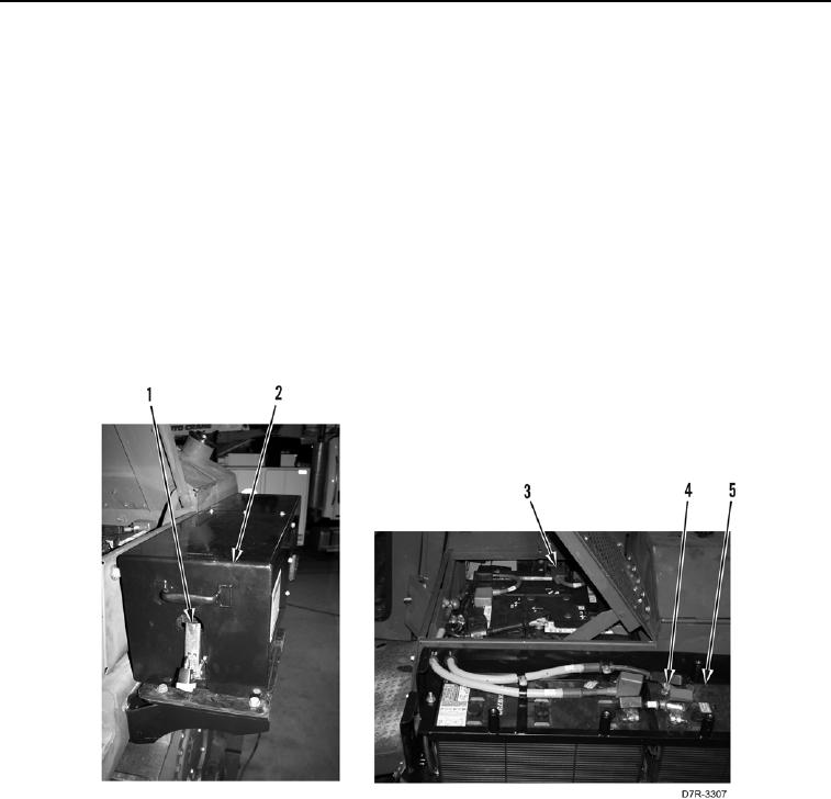
13. Release two latches (Figure 7, Item 1) on arctic kit battery cover (Figure 7, Item 2).
14. With an assistant, remove arctic kit battery cover (Figure 7, Item 2) from machine.
15. Turn battery disconnect switch to OFF position (TM 5-2410-241-10).
16. Disconnect negative arctic kit battery cable from negative post (Figure 7, Item 4) of arctic kit batteries (Figure
7, Item 5).
17. Turn battery disconnect switch to ON position (TM 5-2410-241-10).
18. Using a digital multimeter (WP 0296), measure voltage between positive post (Figure 7, Item 3) of battery and
arctic kit battery cable connector disconnected from negative post (Figure 7, Item 4). Voltage should be within
1 volt of value recorded in step 3 or arctic kit negative battery cable is faulty.
a. If voltage drop is greater than 1 volt of value recorded in step 3, arctic kit negative battery cable is faulty.
Replace arctic kit negative battery cable (WP 0160).
b. If voltage drop is within 1 volt of value recorded in step 3, with an assistant, install arctic kit battery cover
(Figure 7, Item 2) and set two latches (Figure 7, Item 1) on arctic kit battery cover. Proceed to Test Step 2.
Figure 7. Arctic Kit Negative Battery Cable.
0029
END OF TASK