
TM 5-2410-241-23-1
0029
TEST STEP 2: POSITIVE CABLES CONTINUED
00029
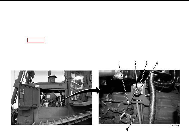
5. Remove cover (Figure 11, Item 1) from NATO slave receptacle (Figure 11, Item 3).
6. Using a digital multimeter (WP 0296), measure voltage drop between inner contact (Figure 11, Item 2) (positive
point) and outer contact (Figure 11, Item 4) of NATO slave receptacle (Figure 11, Item 3). Voltage drop should
be within 1 volt of value recorded in step 1.
a. If voltage drop is greater than 1 volt of value recorded in step 1, replace positive battery cable (Figure 11,
Item 5) (WP 0045) of NATO slave receptacle (Figure 11, Item 3).
b. If voltage drop is within 1 volt of value recorded in step 1, install cover (Figure 11, Item 1) on NATO slave
receptacle (Figure 11, Item 3) and proceed to step 8.
Figure 11. Positive Contact of NATO Slave Receptacle.
0029