
TM 5-2410-241-23-1
0029
TEST STEP 2: POSITIVE CABLES CONTINUED
00029
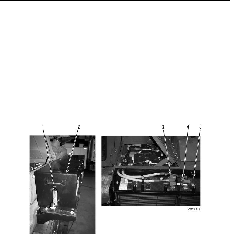
10. Release two latches (Figure 14, Item 1) from arctic kit battery cover (Figure 14, Item 2).
11. With an assistant, remove arctic kit battery cover (Figure 14, Item 2).
12. Turn battery disconnect switch to OFF position (TM 5-2410-241-10).
13. Disconnect arctic kit positive battery cable (Figure 14, Item 3) from arctic kit batteries (Figure 14, Item 5).
14. Turn battery disconnect switch to ON position (TM 5-2410-241-10).
15. Using a digital multimeter (WP 0296), measure voltage drop between arctic kit positive battery cable terminal
(Figure 14, Item 3) and negative battery post (Figure 14, Item 4) of arctic kit battery (Figure 14, Item 5). Voltage
drop should be within 1 volt of value recorded in step 1.
a. If voltage drop is greater than 1 volt of value recorded in step 1, proceed to step 17.
b. If voltage drop is within 1 volt of value recorded in step 1, positive battery cables and positive alternator
cables are OK.
c.
Turn battery disconnect switch to OFF position (TM 5-2410-241-10).
d. Connect arctic kit positive battery cable (Figure 14, Item 3) on arctic kit batteries (Figure 14, Item 5).
e. With an assistant, install arctic kit battery cover (Figure 14, Item 2), and set two latches (Figure 14, Item 1)
on arctic kit battery cover (Figure 14, Item 2).
Figure 14. Arctic Kit Positive Battery Cable.
0029