
TM 5-2410-241-23-1
0029
TEST STEP 2: POSITIVE CABLES CONTINUED
00029
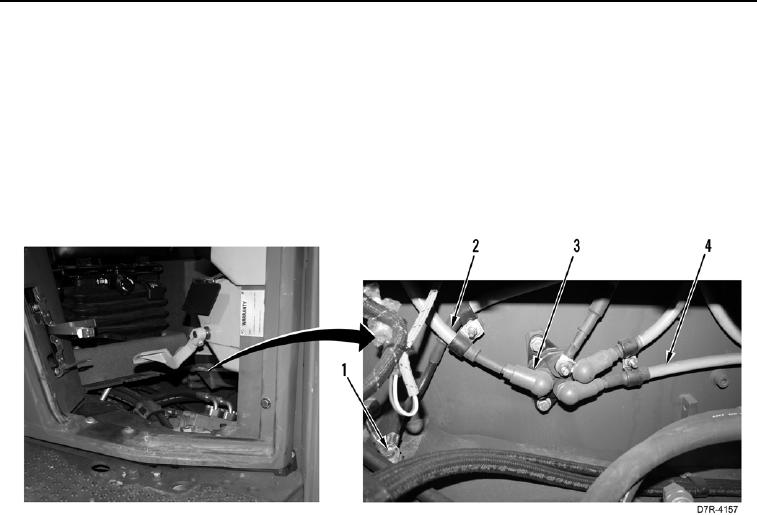
4. Using a digital multimeter (WP 0296), measure voltage between positive terminal (Figure 10, Item 3) of
junction on left side of machine and machine ground (Figure 10, Item 1). Voltage drop should be within 1 volt of
value recorded in step 1.
a. If voltage drop is greater than 1 volt of value recorded in step 1, positive battery cable from positive battery
post (Figure 10, Item 2) to junction block is faulty. Replace positive battery cable from positive battery post
to junction block (WP 0159).
b. If voltage drop is within 1 volt of value recorded in step 1, positive battery cable (Figure 10, Item 4) to
starter is faulty. Replace positive battery cable to starter (WP 0164).
Figure 10. Left Side Positive Battery Cable Junction.
0029