
TM 5-2410-241-23-1
0029
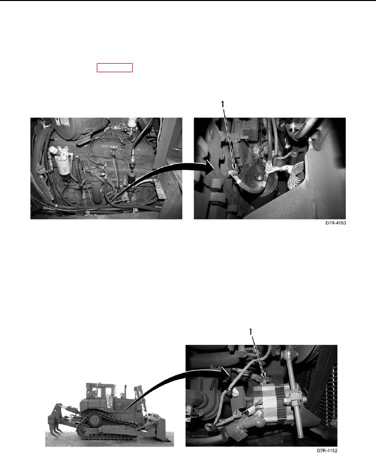
TEST STEP 1: GROUND CABLES CONTINUED
9. Using a digital multimeter (WP 0296), measure voltage between positive post (Figure 4, Item 1) and engine
ground terminal (Figure 4, Item 1). Voltage drop should be within 1 volt of value recorded in step 3 or the
engine ground cable is faulty.
a. If voltage drop is greater than 1 volt of value recorded in step 3, engine ground cable is faulty. Replace
engine ground cable (WP 0049).
b. If voltage drop is within 1 volt of value recorded in step 3, proceed to step 10.
Figure 4. Engine Ground Cable.
0029
10. Using a digital multimeter (WP 0296), measure voltage between positive post (Figure 5, Item 1) and alternator
ground terminal (Figure 5, Item 1). Voltage drop should be within 1 volt of value recorded in step 3 or the
alternator ground strap is faulty.
a. If voltage drop is greater than 1 volt of value recorded in step 3, alternator ground strap is faulty. Replace
alternator ground strap (WP 0163).
b. If voltage drop is within 1 volt of value recorded in step 3, proceed to step 11.
Figure 5. Alternator Ground Connection.
0029