
TM 5-2410-241-23-1
0031
STARTING SYSTEM TESTS CONTINUED
Test Step 5. Testing Starting Motor Solenoid Supply Circuit.
00031
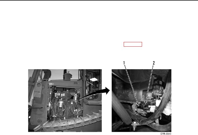
1. Disconnect platform wiring harness connector VC-19 (Figure 4, Item 1) from engine main wiring harness
connector MA-C8 (Figure 4, Item 2).
2. With assistance, monitor the digital multimeter and record voltage between the platform wiring harness
connector VC-19 (Figure 4, Item 1) and ground while attempting to crank the engine (TM 5-2410-241-10).
a. If voltage is 17 to 26 volts, replace engine main wiring harness (WP 0055).
b. If voltage is less than 17 volts, proceed to step 3.
Figure 4. Harness Connector VC-19 and MA-C8.
0031