
TM 5-2410-241-23-1
0031
STARTING SYSTEM TESTS CONTINUED
3. Turn ignition and battery disconnect switch OFF (TM 5-2410-241-10).
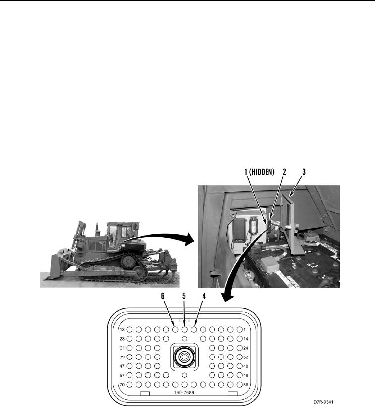
4. Open fuse panel access door (Figure 5, Item 3).
5. Disconnect platform wiring harness connector MA-C3 (Figure 5, Item 2) from fuse panel harness connector A-
C1 (Figure 5, Item 1).
6. Monitor and record the digital multimeter and measure resistance between platform wiring harness connector
MA-C3 terminal 6 (Figure 5, Item 4) and platform harness connector VC-19 (Figure 5, Item 1).
7. Monitor and record the digital multimeter and measure resistance between platform wiring harness connector
MA-C3 terminal 7 (Figure 5, Item 5) and platform harness connector VC-19 (Figure 5, Item 1).
8. Monitor and record the digital multimeter and measure resistance between platform wiring harness connector
MA-C3 terminal 8 (Figure 5, Item 6) and platform harness connector VC-19 (Figure 5, Item 1).
a. If resistance is 5.0 ohms or greater for any measurement, replace platform wiring harness (WP 0209).
b. If resistance is less than 5.0 ohms for all measurements, proceed to step 9.
Figure 5. Harness Connector A-C1 and MA-C3.
0031