
TM 5-2410-241-23-1
0032
BLADE LIFT CYLINDER PRESSURE TEST CONTINUED
N OT E
Steps 8 through 13 will address right cylinder. Repeat steps for left cylinder.
8. Ensure that blade is at rest flat on the ground (TM 5-2410-241-10).
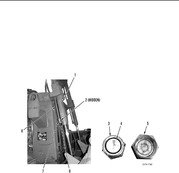
9. Position drain pan underneath cylinder (Figure 3, Item 1).
10. Loosen tube nut (Figure 3, Item 7) and position line (Figure 3, Item 8) aside from fitting (Figure 3, Item 6).
Leave O-ring (Figure 3, Item 2) in place until after test.
11. Install seal 6V-8400 (Figure 3, Item 4) on plug 6V-9513 (Figure 3, Item 3).
12. Install plug 6V-9513 (Figure 3, Item 3) on line (Figure 3, Item 8).
13. Install cap 6V-9834 (Figure 3, Item 5) on fitting (Figure 3, Item 6).
Figure 3. Front Lift Cylinder.
0032