
TM 5-2410-241-23-1
0032
BLADE LIFT CYLINDER PRESSURE TEST - CONTINUED
21. Set machine to LOW IDLE (TURTLE MODE) on the throttle switch (TM 5-2410-241-10).
22. Turn ignition switch and battery disconnect switch to OFF position (TM 5-2410-241-10).
23. Release hydraulic system pressure (WP 0186).
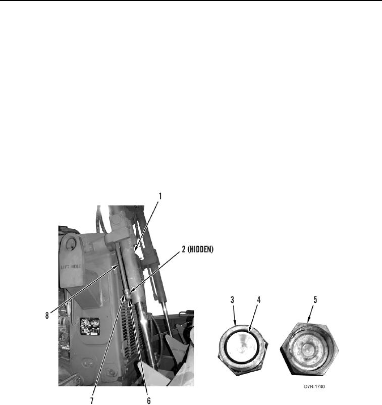
24. Position drain pan underneath cylinder (Figure 5, Item 1)
25. Remove cap 6V-9834 (Figure 5, Item 5) and O-ring (Figure 5, Item 2) from fitting (Figure 5, Item 6). Discard O-
ring.
26. Remove plug 6V-9513 (Figure 5, Item 3) and seal 6V-8400 (Figure 5, Item 4) from line (Figure 5, Item 8).
27. Install new O-ring (Figure 5, Item 2) on fitting (Figure 5, Item 6).
28. Position line (Figure 5, Item 8) on fitting (Figure 5, Item 6).
29. Tighten tube nut (Figure 5, Item 7) on fitting (Figure 5, Item 6).
30. Remove gauges.
31. Reinstall protective caps.
32. Close door (TM 5-2410-241-10).
Figure 5. Front Lift Cylinder.
0032
END OF TASK