
TM 5-2410-241-23-1
0032
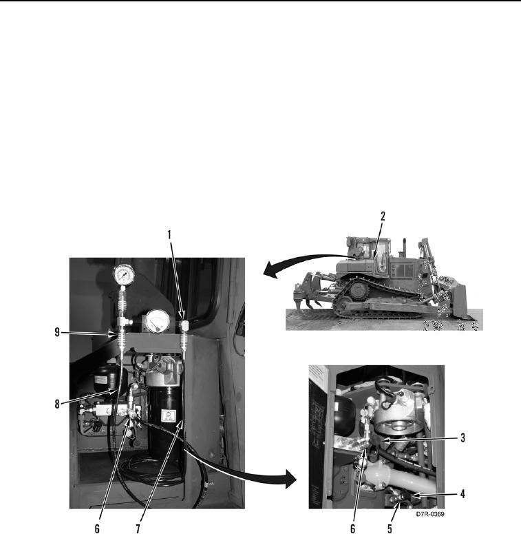
RIPPER LIFT CYLINDER PRESSURE TEST - CONTINUED
00032
3. Open door (Figure 10, Item 2) (TM 5-2410-241-10).
N OT E
Transmission filter shown removed for clarity.
4. Remove protective cap (Figure 10, Item 3) from fitting (Figure 10, Item 6).
5. Remove protective cap (Figure 10, Item 4) from fitting (Figure 10, Item 5).
6. Connect 177-7861 hose (Figure 10, Item 8) coming from implement pump discharge pressure port (Figure 10,
Item 9) to fitting (Figure 10, Item 6).
7. Connect 177-7862 hose (Figure 10, Item 7) coming from signal pressure port (Figure 10, Item 1) to fitting
(Figure 10, Item 5).
Figure 10. Test Equipment Installation.
0032