
TM 5-2410-241-23-1
0032
BLADE LIFT CYLINDER PRESSURE TEST CONTINUED
14. Start machine and allow it to run for 15 minutes to reach normal operating temperature (TM 5-2410-241-10).
15. Set machine to HIGH IDLE (RABBIT MODE) on the throttle switch (TM 5-2410-241-10).
16. Slowly engage blade lift control to the LIFT position (TM 5-2410-241-10).
N OT E
Do not hold control lever in the LIFT position longer than 15 to 20 seconds.
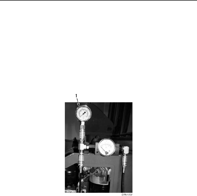
17. Hold blade lift control in the LIFT position (TM 5-2410-241-10) and record pressure shown on the pressure
gauge (Figure 4, Item 1).
18. Pressure gauge (Figure 4, Item 1) should read 3,255 to 3,345 psi (22,450 to 23,050 kPa).
19. If pressure is out of specification, replace bulldozer lift control valve (WP 0211 with Ripper) (WP 0212 with
Winch).
20. Return blade lift control to the CENTER position (TM 5-2410-241-10).
Figure 4. Test Equipment Installation.
0032