
TM 5-2410-241-23-2
0060
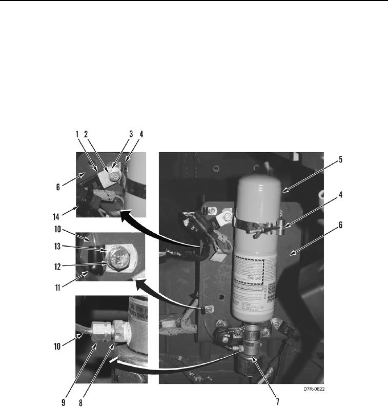
ETHER VALVE AND BOTTLE SUPPORT BRACKET INSTALLATION CONTINUED
11. Position clip (Figure 13, Item 1) and harness (Figure 13, Item 14) on bracket (Figure 13, Item 6).
12. Install clamp (Figure 13, Item 4), clip (Figure 13, Item 1), two washers (Figure 13, Item 3), and bolts (Figure 13,
Item 2) on bracket (Figure 13, Item 6).
13. Install clamps (Figure 13, Item 11), two washers (Figure 13, Item 13), and bolts (Figure 13, Item 12) on line
(Figure 13, Item 10).
14. Install line (Figure 13, Item 10) and tube nut (Figure 13, Item 9) on fitting (Figure 13, Item 8).
15. Install bottle (Figure 13, Item 5) on clamp (Figure 13, Item 4) and ether valve (Figure 13, Item 7).
16. Tighten clamp (Figure 13, Item 4) on bottle (Figure 13, Item 5).
Figure 13. Ether Bottle and Line.
0060
END OF TASK