
TM 5-2410-241-23-2
0126
REMOVAL CONTINUED
N OT E
Tag and mark hoses and lines to aid installation.
Cap and plug all open hoses and ports to avoid contamination.
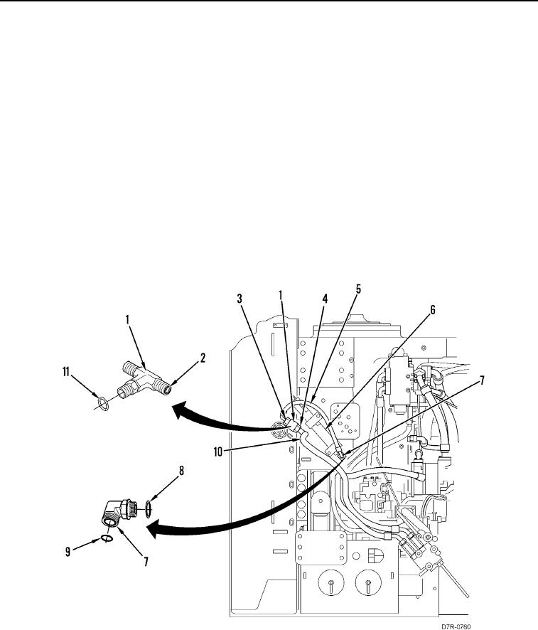
2. Loosen two tube nuts (Figure 2, Item 3) and remove hose (Figure 2, Item 5) from tee (Figure 2, Item 1) and
elbow (Figure 2, Item 7).
3. Loosen tube nut (Figure 2, Item 4) and remove hose (Figure 2, Item 10) from tee (Figure 2, Item 1).
4. Remove tee (Figure 2, Item 1) and three O-rings (Figure 2, Items 2 and 11) from machine. Discard O-rings.
5. Remove accumulator (Figure 2, Item 6) from machine.
N OT E
Note orientation of elbow to aid installation.
6. Remove elbow (Figure 2, Item 7) and two O-rings (Figure 2, Items 8 and 9) from accumulator (Figure 2,
Item 6). Discard O-rings.
Figure 2. Threaded Fitting Type Hydraulic Hose.
0126
END OF TASK