
TM 5-2410-241-23-2
0162
INSTALLATION CONTINUED
N OT E
Install cables as tagged during removal.
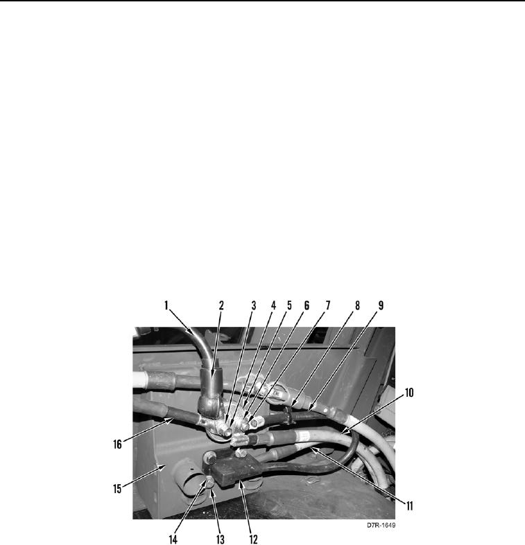
5. Install junction block power cable (Figure 4, Item 11), receptacle ground cable (Figure 4, Item 9), four washers
(Figure 4, Item 14), and bolts (Figure 4, Item 13) on front battery box cover (Figure 4, Item, 15).
6. Install battery disconnect switch (Figure 4, Item 5) on machine.
7. Install ground cable (Figure 4, Item 10), receptacle ground cable (Figure 4, Item 9), new lockwasher (Figure 4,
Item 6), and nut (Figure 4, Item 7) on battery disconnect switch (Figure 4, Item 5).
8. Install new tiedown strap (Figure 4, Item 8) on receptacle ground cable (Figure 4, Item 9).
N OT E
Arctic kit negative battery cable shown for machines equipped with arctic kit.
Install cables as noted during removal.
9. Install arctic kit ground battery cable (Figure 4, Item 16), negative battery cable (Figure 4, Item 1), new
lockwasher (Figure 4, Item 4), and nut (Figure 4, Item 3) on battery disconnect switch (Figure 4, Item 5).
10. Position boot (Figure 4, Item 2) on negative battery cable (Figure 4, Item 1).
Figure 4. Receptacle and Battery Disconnect Switch Connections.
0162