
TM 5-2410-241-23-2
0162
REMOVAL CONTINUED
N OT E
Note cable and clamp routing to aid installation.
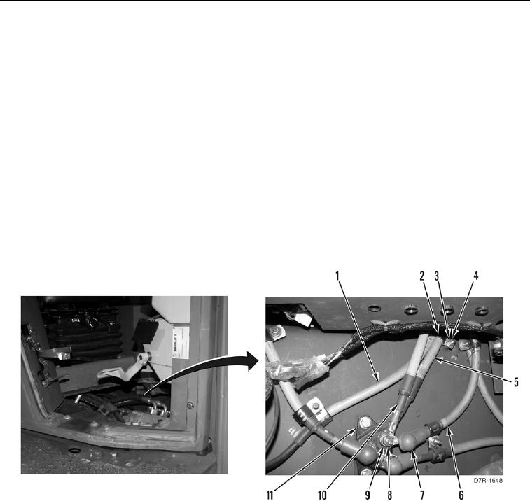
10. Remove locknut (Figure 3, Item 4), washer (Figure 3, Item 3), and clamp (Figure 3, Item 2) from receptacle
ground cable (Figure 3, Item 1) and junction block power cable (Figure 3, Item 5). Discard locknut.
11. Position boot (Figure 3, Item 7) aside.
N OT E
Arctic kit power battery cable shown for machines equipped with arctic kit.
Note cable and clamp routing to aid installation.
12. Remove nut (Figure 3, Item 8), lockwasher (Figure 3, Item 9), fuse panel power cable (Figure 3, Item 6), arctic
kit power battery cable (Figure 3, Item 10), and junction block power cable (Figure 3, Item 5) from junction
block (Figure 3, Item 11). Discard lockwasher.
13. Remove junction block power cable (Figure 3, Item 5) from machine.
Figure 3. Receptacle Cable at Junction Block.
0162
END OF TASK
CLEANING AND INSPECTION
000162
Clean and inspect all parts IAW Mechanical General Maintenance Instructions (WP 0295).
END OF TASK