
TM 5-2410-241-23-3
0216
DISASSEMBLY CONTINUED
N OT E
Note orientation and position of fittings to aid assembly.
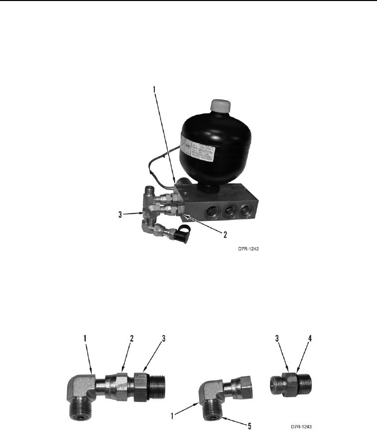
26. Remove fitting (Figure 10, Item 2) and elbow (Figure 10, Item 3) from control manifold (Figure 10, Item 1).
Figure 10. Control Manifold Assembly Elbow Fitting.
0216
27. Loosen tube nut (Figure 11, Item 2) and remove elbow assembly (Figure 11, Item 1) from fitting (Figure 11,
Item 3).
28. Remove two O-rings (Figure 11, Item 4) from fitting (Figure 11, Item 3). Discard O-rings.
29. Remove O-ring (Figure 11, Item 5) from elbow assembly (Figure 11, Item 1). Discard O-ring.
Figure 11. Elbow Fitting Disassembly.
0216