
TM 5-2410-241-23-3
0216
DISASSEMBLY CONTINUED
N OT E
Note orientation and position of fittings to aid installation.
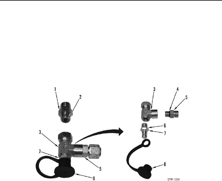
16. Remove two O-rings (Figure 7, Item 2) from fitting (Figure 7, Item 1). Discard O-rings.
17. Remove fitting (Figure 7, Item 5) from T fitting (Figure 7, Item 3).
18. Remove O-ring (Figure 7, Item 4) from fitting (Figure 7, Item 5). Discard O-ring.
19. Remove cover and strap (Figure 7, Item 8) from diagnostic port fitting (Figure 7, Item 7).
20. Remove diagnostic port fitting (Figure 7, Item 7) from T fitting (Figure 7, Item 3).
21. Remove O-ring (Figure 7, Item 6) from diagnostic port fitting (Figure 7, Item 7). Discard O-ring.
Figure 7. Diagnostic Port Fitting Disassembly.
0216