
TM 5-2410-241-23-3
0216
REMOVAL CONTINUED
N OT E
Plug all lines, hoses and tubes to prevent contamination.
Tag and mark lines to aid installation.
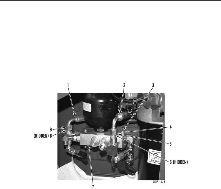
4. Loosen tube nut (Figure 3, Item 9) and remove hose (Figure 3, Item 1) and O-rings (Figure 3, Item 8) from
control manifold (Figure 3, Item 7). Discard O-rings.
5. Loosen tube nut (Figure 3, Item 5) and remove hose (Figure 3, Item 2) and O-rings (Figure 3, Item 6) from
control manifold (Figure 3, Item 7). Discard O-rings.
6. Remove two bolts (Figure 3, Item 3), washers (Figure 3, Item 4), and control manifold (Figure 3, Item 7) from
machine.
Figure 3. Control Valve Hoses.
0216
END OF TASK