
TM 5-2410-241-23-3
0215
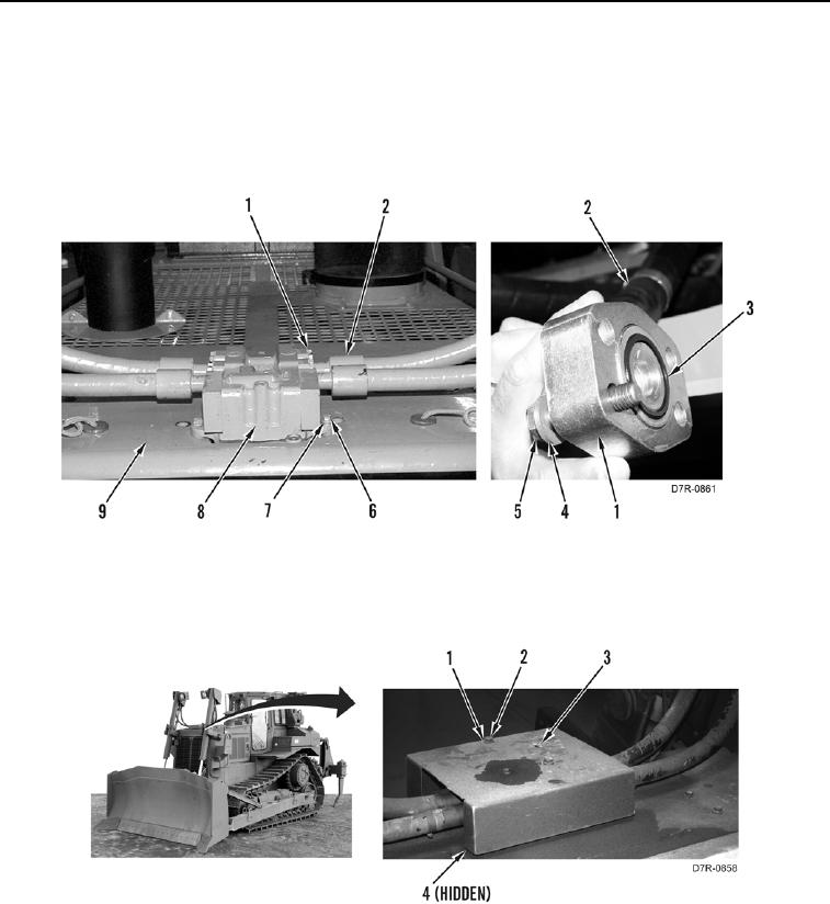
INSTALLATION CONTINUED
4. Install three washers (Figure 5, Item 7) and bolts (Figure 5, Item 6) on quick drop valve (Figure 5, Item 8) and
hood (Figure 5, Item 9).
5. Install four new O-rings (Figure 5, Item 3) on hoses (Figure 5, Item 2).
6. Install 4 hoses (Figure 5, Item 2), flanges (Figure 5, Item 1), 16 washers (Figure 5, Item 4), and bolts (Figure 5,
Item 5) on quick drop valve (Figure 5, Item 8).
Figure 5. Upper Hoses.
0215
7. Install cover (Figure 6, Item 3), three washers (Figure 6, Item 1), and bolts (Figure 6, Item 2) on quick drop
valve (Figure 6, Item 4).
Figure 6. Valve Cover.
0215