• Home
  • Download PDF
  • Order CD-ROM
  • Order in Print
CONTROL MANIFOLD SERVICE
Figure 2. Control Valve Line.

Field Maintenance Manual 3 D7R Dozer Type I With Winch and Type II With Ripper
Page Navigation
  280    281    282    283    284  285  286    287    288    289    290  
img
.
TM 5-2410-241-23-3
0216
REMOVAL
000216
N OT E
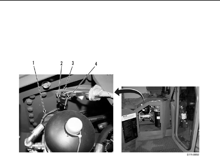
Tag and mark all electrical connections to aid installation.
1. Remove tiedown strap (Figure 1, Item 2) from connector (Figure 1, Item 3) and bracket (Figure 1, Item 4).
Discard tiedown strap.
2. Disconnect connector (Figure 1, Item 3) and position harness (Figure 1, Item 1) aside.
Figure 1. Electrical Connector.
0216
0216-2


Privacy Statement
Press Release
Contact

© Copyright Integrated Publishing, Inc.. All Rights Reserved.