• Home
  • Download PDF
  • Order CD-ROM
  • Order in Print
Figure 5. Sampling Valve and Fittings Disassembly.
Figure 7. Diagnostic Port Fitting Disassembly.

Field Maintenance Manual 3 D7R Dozer Type I With Winch and Type II With Ripper
Page Navigation
  285    286    287    288    289  290  291    292    293    294    295  
img
.
TM 5-2410-241-23-3
0216
DISASSEMBLY CONTINUED
N OT E
Note orientation and position of fittings to aid assembly.
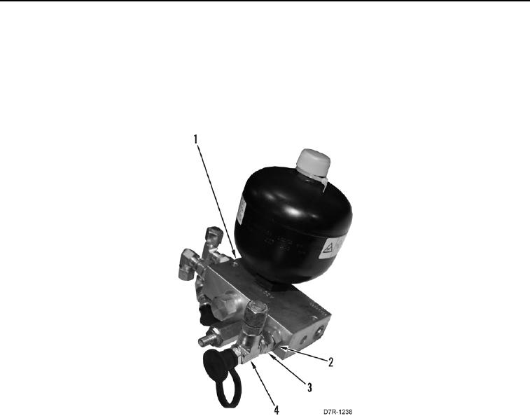
14. Loosen tube nut (Figure 6, Item 3) and remove fitting assembly (Figure 6, Item 4) from fitting (Figure 6, Item 2).
15. Remove fitting (Figure 6, Item 2) from control manifold (Figure 6, Item 1).
Figure 6. Control Manifold Assembly Diagnostic Port Fitting.
0216
0216-7


Privacy Statement
Press Release
Contact

© Copyright Integrated Publishing, Inc.. All Rights Reserved.