
TM 5-2410-241-23-3
0216
DISASSEMBLY
000216
N OT E
Note orientation and position of fittings to aid assembly.
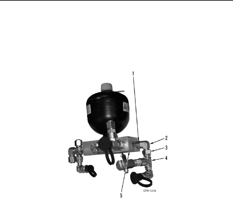
1. Loosen tube nut (Figure 4, Item 3) and position T fitting (Figure 4, Item 4) out from under control manifold
(Figure 4, Item 5).
2. Loosen tube nut (Figure 4, Item 1) and remove fitting assembly (Figure 4, Item 2) from control manifold
(Figure 4, Item 5).
Figure 4. Control Manifold Assembly Sampling Valve and Fitting.
0216