
TM 5-2410-241-23-3
0296
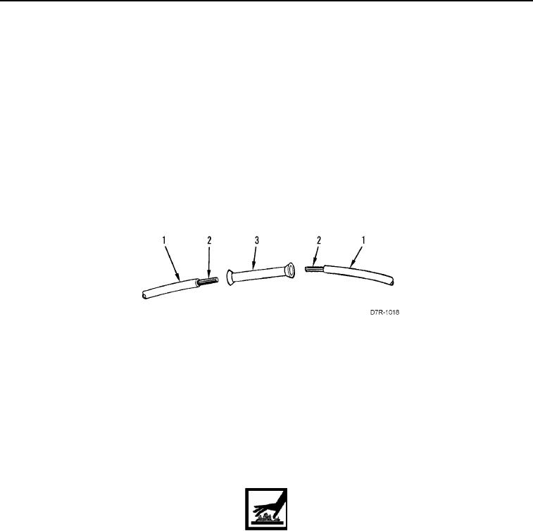
SPLICING WIRES
000296
N OT E
The use of high quality splice connectors is essential to ensure optimum electrical
integrity. Use the type and size connector best suited to the application.
1. Inspect each end of wire (Figure 2, Item 1). Trim insulation and metal strands (Figure 2, Item 2) of wire back,
as necessary, to ensure integrity of wire.
2. Using wire stripping tool, strip each end of wire (Figure 2, Item 1) to expose length of metal strands (Figure 2,
Item 2) suitable for size of splice connector (Figure 2, Item 3).
3. Insert metal strands (Figure 2, Item 2) of each wire (Figure 2, Item 1) fully into splice connector (Figure 2,
Item 3).
4. Securely crimp splice connector (Figure 2, Item 3) to metal strands (Figure 2, Item 2) and to insulation of wire
(Figure 2, Item 1).
Figure 2. Splicing Wires.
0296
END OF TASK
HEAT-SHRINKABLE TUBING (ELECTRICAL INSULATING SLEEVING)
000296
Use heat-shrinkable tubing to insulate soldered and crimped electrical connections.
a. Cut length of new heat-shrinkable tubing twice as long as connection to be covered.
b. Slide heat-shrinkable tubing onto wire and out of the way before making electrical connection.
c.
After making electrical connection, slide heat-shrinkable tubing into place over electrical connection.
WARN I N G
Do not touch heat-shrinkable tubing for at least 30 seconds after heating. Heat-shrinkable
tubing is hot and will cause burns.
d. Using heat gun, apply heat to heat-shrinkable tubing for approximately 30 seconds, until tubing forms to
shape of electrical connection.
END OF TASK