
TM 5-2410-241-23-3
0296
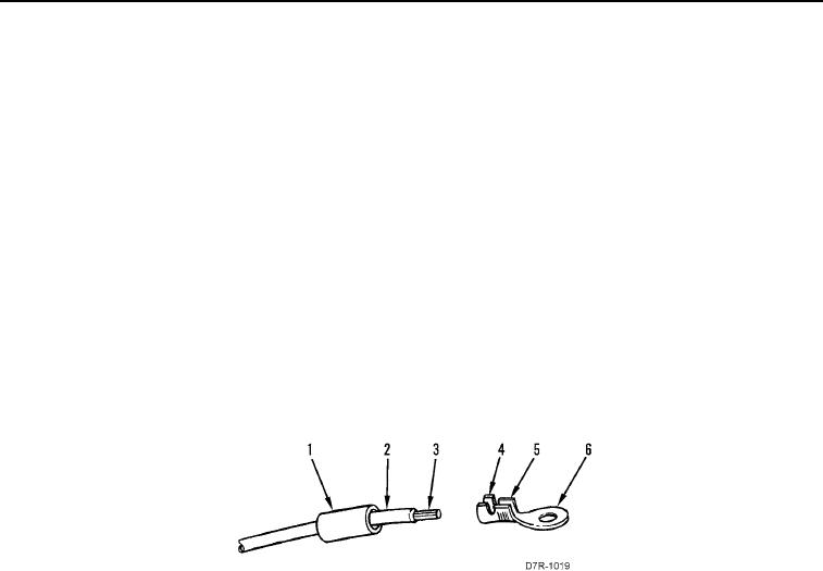
RING TERMINAL REPAIR
000296
1. Remove ring terminal (Figure 3, Item 6) from wire (Figure 3, Item 2) by cutting through wire just behind heat-
shrinkable tubing (Figure 3, Item 1).
2. Cut heat-shrinkable tubing (Figure 3, Item 1) of sufficient length to cover tabs (Figure 3, Items 4 and 5) of ring
terminal (Figure 3, Item 6) and 1/4 in. (6 mm) of wire (Figure 3, Item 2).
3. Slide heat-shrinkable tubing (Figure 3, Item 1) back on wire (Figure 3, Item 2).
4. Using wire stripping tool, strip insulation from wire (Figure 3, Item 2) to expose proper length of metal strands
(Figure 3, Item 3).
5. Using crimping tool, securely crimp tabs (Figure 3, Item 5) of ring terminal (Figure 3, Item 6) over metal strands
(Figure 3, Item 3).
6. Using crimping tool, crimp tabs (Figure 3, Item 4) of ring terminal (Figure 3, Item 6) over insulation of wire
(Figure 3, Item 2).
7. Slide heat-shrinkable tubing (Figure 3, Item 1) over crimped tabs (Figure 3, Items 4 and 5) of ring terminal
(Figure 3, Item 6).
8. Using heat gun, apply heat to heat-shrinkable tubing (Figure 3, Item 1) until tubing snugly conforms to ring
terminal (Figure 3, Item 6) and insulation of wire (Figure 3, Item 2).
Figure 3. Ring Terminal Repair.
0296
END OF TASK