
TM 5-2410-240-23-2
0072
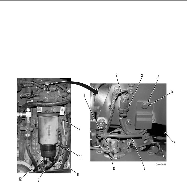
PRIME PUMP LEVEL SENSOR REMOVAL
00072
N OT E
Tag wires and wiring harnesses to aid installation.
1. Disconnect harness (Figure 3, Item 7) from probe (Figure 3, Item 12) and remove three tiedown straps
(Figure 3, Items 9, 10, 11) from harness. Position harness aside. Discard tiedown straps.
2. Remove tiedown strap (Figure 3, Item 1) from bracket (Figure 3, Item 8). Discard tiedown strap.
3. Remove tiedown strap (Figure 3, Item 3) and disconnect engine harness (Figure 3, Item 2) from liquid level
sensor (Figure 3, Item 6). Discard tiedown strap.
4. Remove bolt (Figure 3, Item 5), washer (Figure 3, Item 4), and liquid level sensor (Figure 3, Item 6) from
machine.
Figure 3. Prime Pump Level Sensor.
0072
END OF TASK
CLEANING AND INSPECTION
00072
Clean and inspect all parts IAW Mechanical General Maintenance Instructions (WP 0282).
END OF TASK