
TM 5-2410-240-23-2
0071
INSTALLATION
1. Install switch (Figure 2, Item 2), identification tag (Figure 2, Item 5), washer (Figure 2, Item 3), and nut
(Figure 2, item 4) on base (Figure 2, Item 1).
N OT E
Install wires and wiring harnesses as noted during removal.
Install new tiedown straps as noted during removal.
2. Position harness (Figure 2, Item 7) and connect connector (Figure 2, Item 8).
3. Install two new tiedown straps (Figure 2, Items 6 and 9) on harness (Figure 2, Item 7).
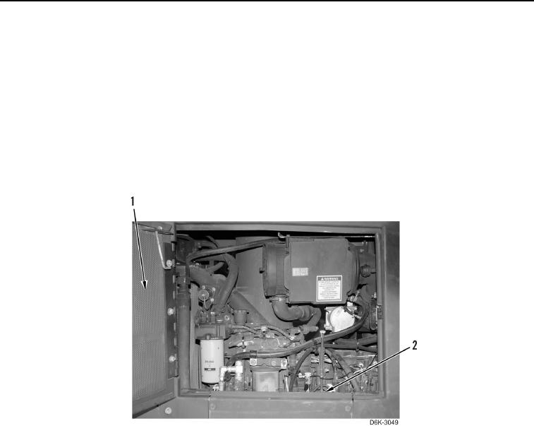
4. Install panel (Figure 3, Item 2) and close left engine door (Figure 3, Item 1).
Figure 3. Left Engine Door.
0071
END OF TASK
FOLLOW-ON TASKS
00071
Verify correct operation of machine (TM 5-2410-240-10).
END OF TASK
END OF WORK PACKAGE
0071-3/(4 blank)