
4
TM 5-2410-240-23-2
FIELD MAINTENANCE
-
PUMP COUPLING REPLACEMENT
009
6
Pump CouplingFlywheel Removal, Pump CouplingPump Removal, Cleaning and Inspection,
Pump CouplingPump Installation, Pump CouplingFlywheel Installation
INITIAL SETUP
References
Tools and Special Tools
0
0
Tool Kit, General Mechanic's
WP 0282
0
(WP 0289, Item 51)
0
Equipment Conditions
0
Screwdriver Attachment Set, Metric, Hex, ID
Machine parked (TM 5-2410-240-10)
Items (S0305) (WP 0289, Item 53)
0
0
Engine removed (WP 0051)
Wrench, Torque, Click, Ratcheting, 1/2" Drive,
0
250 lb-ft (WP 0289, Item 57)
0
Drawing Required
0
Materials/Parts
TM 5-2410-240-24P, Figure 34
0
0
Rag, wiping (WP 0290, Item 21)
0
Estimated Time to Complete
0
Sealing compound 577 (WP 0290, Item 28)
0
0.5 Hr
0
PUMP COUPLINGFLYWHEEL REMOVAL
00096
N OT E
Note position of coupling assembly to aid installation.
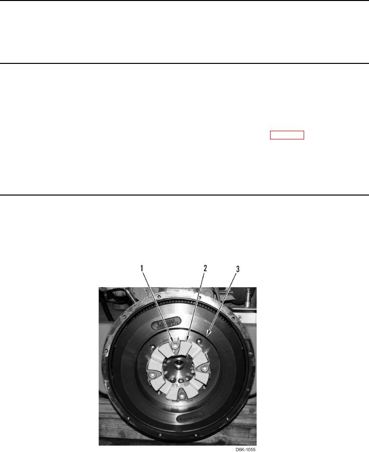
Remove four bolts (Figure 1, Item 1) and coupling assembly (Figure 1, Item 2) from flywheel (Figure 1, Item 3).
Figure 1. Flywheel.
0096
END OF TASK