• Home
  • Download PDF
  • Order CD-ROM
  • Order in Print
Figure 1. Starter and Positive Cables.
Figure 3. Starter, Engine Harness, and Mounting Hardware.

Field Maintenance Manual 2 D6K Dozer Type I With Winch and Type II With Ripper
Page Navigation
  469    470    471    472    473  474  475    476    477    478    479  
img
.
TM 5-2410-240-23-2
0095
REMOVAL CONTINUED
N OT E
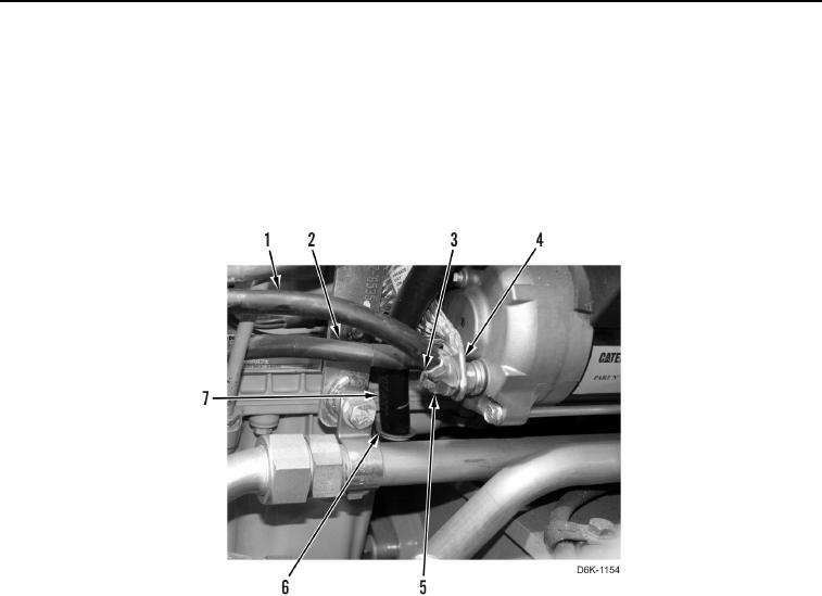
Tag and mark cables to aid installation.
3. Remove nut (Figure 2, Item 5) and three ground cables (Figure 2, Items 1, 2, and 4) from stud
(Figure 2, Item 3).
4. Remove tube (Figure 2, Item 7) from bracket (Figure 2, Item 6) and position tube aside.
Figure 2. Starter and Ground Cables.
0095
0095-3


Privacy Statement
Press Release
Contact

© Copyright Integrated Publishing, Inc.. All Rights Reserved.