
TM 5-2410-240-23-2
0095
INSTALLATION
1. Install three studs (Figure 3, Item 5) on housing (Figure 3, Item 3).
2. Install starter (Figure 3, Item 1) on housing (Figure 3, Item 3).
N OT E
M10 and M12 nuts require different torque specifications.
3. Install three nuts (Figure 3, Item 4) on studs (Figure 3, Item 5). Torque M10 nuts to 24 to 40 lb-ft (33 to 55 Nm).
Torque M12 nuts to 43 to 71 lb-ft (58.3 to 96.2 Nm).
N OT E
Install electrical connectors and tiedown strap as noted during removal.
4. Connect engine harness (Figure 3, Item 2) on starter connector (Figure 3, Item 6).
5. Install new tiedown strap (Figure 3, Item 7) on engine harness (Figure 3, Item 2) and starter connector
(Figure 3, Item 6).
N OT E
Install cables as noted during removal.
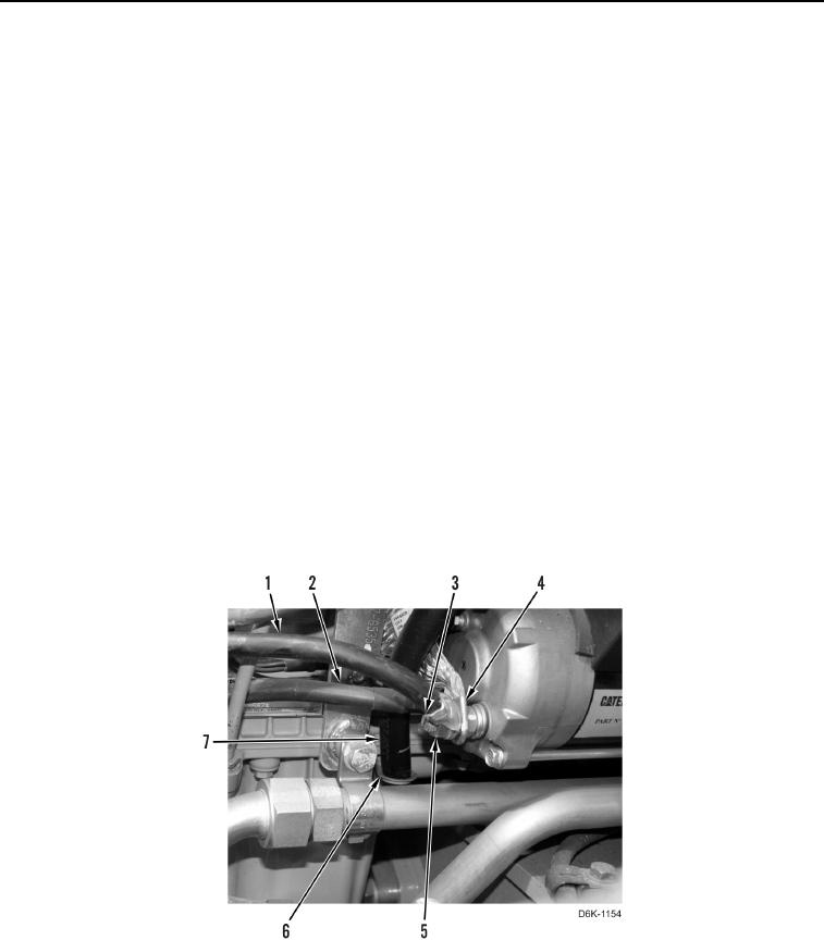
6. Install three ground cables (Figure 4, Items 1, 2, and 4) and nut (Figure 4, Item 5) on stud (Figure 4, Item 3).
Torque nut to 18 lb-ft (25 Nm).
7. Install tube (Figure 4, Item 7) on bracket (Figure 4, Item 6).
Figure 4. Starter and Ground Cables.
0095