
TM 5-2410-240-23-2
0126
REMOVAL CONTINUED
N OT E
Tag and mark electrical connectors to aid installation.
Note position of tiedown straps to aid installation.
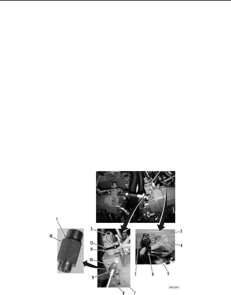
8. Remove tiedown strap (Figure 2, Item 6) from harness (Figure 2, Item 5) and sensor (Figure 2, Item 4). Discard
tiedown strap.
9. Disconnect harness (Figure 2, Item 5) from sensor (Figure 2, Item 4).
10. Remove two bolts (Figure 2, Item 3) and sensor (Figure 2, Item 4) from drive motor (Figure 2, Item 7).
N OT E
Steps 11 through 13 apply to right drive motor only.
Tag, mark, and note routing of hoses to aid installation.
Cap or plug all hydraulic hoses and fittings.
11. Loosen nut (Figure 2, Item 9) and disconnect hose (Figure 2, Item 8) from fitting (Figure 2, Item 10) and
remove hose from machine.
12. Remove fitting (Figure 2, Item 10) from drive motor (Figure 2, Item 7).
13. Remove two O-rings (Figure 2, Item 1) from fitting (Figure 2, Item 10). Discard O-rings.
N OT E
Tag and mark electrical connectors to aid installation.
Note position of tiedown straps to aid installation.
14. Remove tiedown strap (Figure 2, Item 12) from harness (Figure 2, Item 2) and solenoid (Figure 2, Item 11).
Discard tiedown strap.
15. Disconnect harness (Figure 2, Item 2) from solenoid (Figure 2, Item 11). Position harness aside.
Figure 2. Sensor, Fitting, and Hose on Drive Motor.
0126